Contact Us
CHN
  • Energy Storage Controller
  • Energy Storage Controller

EMS

Energy Storage Controller

• Seamless connection between EMS and BMS.

• Integration of Level 3 BAU and EMS.

• Supports multiple types of device access such as Ethernet, CAN, RS485, IO, etc.

• Support OTA software for the entire site system.

• Support local and cloud storage of operational data and event data.

• Support multiple modes such as independent operation, parallel operation, multi-level master-slave operation, etc.

Energy Storage Controller
Product Introduction Video Showcase Insurance Page Testing and Certification Product Parameters Application Cases
Product Introduction

Energy storage controller is an intelligent device that integrates multiple control strategies and algorithms, used for precise management of battery charging and discharging processes, optimizing the operational efficiency and service life of energy storage systems. It can work in conjunction with battery management systems (BMS), energy storage inverters (PCS) and other devices to achieve comprehensive management of energy storage systems.

Application
Peak shaving and frequency regulation of power grid

Release energy storage during peak load periods and charge during low load periods to optimize grid operation efficiency.

Renewable energy access

Smooth out the output fluctuations of renewable energy sources such as solar and wind power, and enhance the stability of the power grid.

Microgrid operation

Provide stable power support during isolated operation of microgrids to ensure the power quality of local users.

Industrial and commercial energy storage

Reduce electricity costs and improve economic benefits through peak shaving, valley filling, demand control, and other methods.

Virtual Power Plant

As an edge node of a virtual power plant, participate in the demand side response of the power grid and optimize energy scheduling.

Electric vehicle charging

Optimize charging strategies, improve charging efficiency, and reduce load pressure on the power grid.

Home energy storage

Combining photovoltaic systems to achieve self-sufficiency in household electricity consumption and ensure basic electricity needs during power outages.

Charge and discharge management

Control the charging and discharging process of the battery, including constant current charging, constant voltage charging, trickle charging, discharge cut-off, etc., to prevent overcharging and overdischarging and extend the battery life.

Status monitoring and data analysis

Real time monitoring of battery voltage, current, temperature, and other conditions, recording charging and discharging data, analyzing battery performance, and providing a basis for system optimization.

Energy scheduling and optimization

Intelligent scheduling of energy storage and release based on grid demand, battery status, and electricity price signals, achieving functions such as peak shaving and valley filling, demand control, frequency and voltage regulation.

Communication and compatibility

Supports multiple communication protocols such as Modbus, MQTT, IEC104, etc., and can be used with photovoltaic inverters BMS、 Seamless integration of charging stations and other equipment.

Parameter

Equipment project

Specifications

CPU

ARM Cortex series quad core processors

Power supply

12VDC,15A

Working power consumption

Under 12VDC, the average power consumption in idle state (no lights on, no 4G communication) is less than 7W;

Working temperature

-30℃~+65℃

Storage temperature

-40℃~ +85℃

External dimensions

Maximum external dimensions: 245mm*169mm

Short distance wireless

One channel Bluetooth interface, working in basic mode or low-power mode

One channel WIFI interface, integrated with Bluetooth on the same module
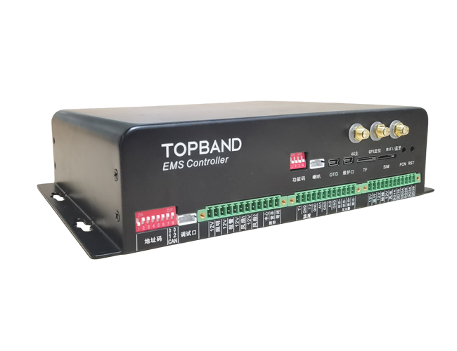
Wireless 4G

One PCIE can be plugged into a full network 4G communication module, with the option of GPS.

SIM card slot

1 SIM card interface, insert half sized card
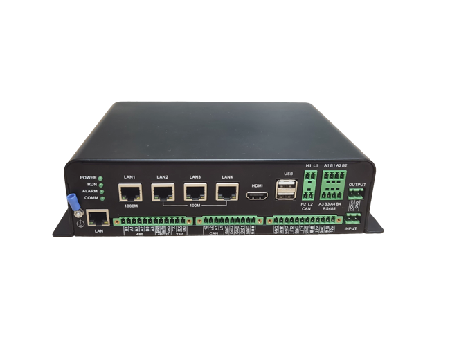
Network port

1 separate network segment network port

3 network ports in the same network segment

USB

2-channel USB

1 OTG USB (for program debugging)

Serial communication

The motherboard (upper layer) is equipped with four RS485 serial ports (switching between sending and receiving signals, requiring the other party to delay sending back for 2ms)

The sub board (lower layer) is equipped with four RS485 serial ports (switching between sending and receiving signals, requiring the other party to delay sending back for 2ms) and one RS232 serial port.

Debug UART

Motherboard (upper layer) 1 channel, MINUSB form, can be connected to a PC through a USB cable, super terminal to view debugging information.

Sub board (lower layer) with a single-chip microcontroller simulation needle burning 4PIN port holder.

CAN

Motherboard (upper layer) has 2 CAN ports, each equipped with a 120 ohm terminal resistor. CAN1 port is internally connected to CAN1 port of the secondary board.

Sub board (lower layer) has 2 CAN ports, each equipped with a 120 ohm terminal resistor, which can be connected or disconnected by the rightmost two positions of the 8-bit dip switch.

Voice

1 speaker interface, volume less than 1.5W, external 8-ohm speaker.

Hard drive

Internally provides SATA signal and 5VDC socket for power supply, and can be optionally connected to a portable hard drive.

High definition display port

HDMI Type A socket (HDMI-19plug Type A) with one channel; Reserve a 12VDC power output for one screen.

Key

1 RST reset key, 1 function key

Indicator light

1 power indicator light, 3 status indicator lights

Buzzer

Internal 1

TF card holder

1pcs, used for burning programs

RTC

Internal 1, can be equipped with CR2032-3V_200mAh battery for RTC clock power supply

State input

Reserve 2 status detection channels (empty node input, the same below)

One channel circuit breaker status detection

One channel lightning protection status detection

2-channel door status detection

One channel smoke detection status detection

One channel water level status detection

One channel fire protection status detection

Switching output

One channel lighting control output, DC12V MAX 1A

One channel alarm control output, DC12V MAX 1A

2-channel DC fan control output, DC12V MAX 1A

One channel trip control output (contact capacity AC250V 3A or DC30V 3A)

One channel fire control output, DC12V greater than 700mA electric start, start pulse maintained for more than 1 second duration

3-channel external status light control outputs, DC12V maximum 1A

3-channel reserved relay control output, contact capacity 250VAC 1A

Analog input

2-channel 0-5V DC analog AD input

2-channel NTC 10K B3950 temperature sensor input

Communication address setting

The sub board has a 6-digit dip switch for setting the communication address of CAN port 1, which is used by default to communicate with the main board

Digital temperature sensing

There is a DS18B20 digital temperature sensor on the secondary board, which is used to measure the internal air temperature of the device.
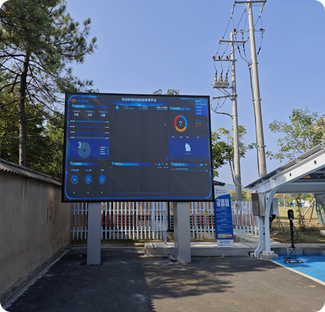
Cloud management

Support

Network timing

Support NTP/RTC clock synchronization


Customer Testimonials
What Our Clients Say

We supply clients across the entire globe with improved network connections.

4.6/5 ( From 600+ reviews )
  • Photovoltaic energy storage and charging system is an energy system that integrates photovoltaic power generation ...
  • 1 Photovoltaic energy storage and charging system is an energy system that integrates photovoltaic power generation ...
Topband
Related Products
Get In Touch

We love questions and feedbacks. and we're always happy to help! Send us a message and we'll respond as soon as possible.

Energy Storage Controller

New Energy
Mobile Energy Storage Energy Storage Cabinet Stacked Energy Storage PEDF Energy Gateway EMS Photovoltaic Equipment
Power
Low voltage switchgear High voltage switchgear Three boxes and supporting Box type transformer
Solution
Photovoltaic storage charging Commercial complex Manufacturing Smart Farm
News
Company News Industry News
Service
Product Brochure User Manual Promotion Video Operation Tutorial FAQs
About Us
Company Overview Company Honors Global Layout

Address:Topband Industrial Park, Liyuan Industrial Zone, Shiyantangtou Avenue, Bao'an District, Shenzhen.

Tel:0755-8178 5236

E-mail:topband_zidh@topband.com.cn

1996-2024@ Shenzhen Topband Automation Technology Co., Ltd. Copyright Powered by szzghlWebsite Map